Passives
The voltage-dependent ceramic chip capacitor
The ceramic capacitor’s low cost, ability to withstand temperature extremes, and a wide availability of capacitance values make them extremely attractive for bypass, power and even signal applications.
Buried deep in the plethora of charts and curves that describe the performance of these components is the “capacitance vs. voltage” characteristic curve. This article will examine and discuss the subject, explain how to test this characteristic, and what to do about it if your design requires inexpensive or small packages, or both.
Circuit designers often overlook the fact that most ceramic capacitors will not have their specified capacitance when placed into the real world with a DC bias across them, such as in bypass applications, or if one is used for DC blocking in signal circuitry. C0G and NPO type capacitors that use class 1 dielectrics are exceptions. They have extremely low change in capacitance over their voltage range, and a low temperature coefficient of capacitance. What may be a problem for a circuit design: they are considerably larger and they are more expensive. Manufacturers are working to reduce at least the size of class 1 capacitors by tweaking dielectric formulations and film thickness. For those who are chemically curious, one of these tweaks is to change C0G dielectric materials from barium neodymium titanate (BNT) to base metal electrode (BME) C0G dielectrics. These are mainly based on calcium zirconate (CaZrO3).
It will be helpful to review the two types of dielectrics used in ceramic chip capacitors.
Class 1 dielectrics are extremely stable over voltage and temperature and display very little aging. By far the most common type of capacitor using Class 1 dielectrics is C0G (also known as NPO). Given equal capacitance values, these capacitors are much larger in size than those that use class 2 dielectrics because the relative permittivity of the materials is lower. Common class 2 types include X7R, X5R, Z5U and Y5V. This article is primarily for those who must use the smaller and less expensive class 2 parts.
[Learn more about ceramic capacitors on GlobalSpec.com]Capacitors of the same brand, dielectric and voltage rating often have a completely different curve of voltage dependency. In one known case, a manufacturer’s 1206 part lost 3% of capacitance over its voltage range and its 0805 lost 50%.
Testing the voltage dependency
During the breadboarding, prototype or pilot run characterization of a product using Class 2 or above ceramic capacitors, one might want to really KNOW the capacitances at the DC voltage that will be present when the circuit is in operation. The same can be said for the qualification of a manufacturer or part number. If so, there are a few ways to test and characterize voltage versus capacitance curve. Which way is selected will depend on available time, equipment budget and the number of capacitors to test.
The slow, inexpensive way: the designer has a general purpose digital multi-meter (DMM) with capacitance function, but if a bias voltage is applied while testing the meter can be damaged and the readings will not be accurate. To use a DMM to make these measurements, connect one end of the capacitor under test (CUT) to one lead of the DMM and one lead of the bias power supply. Connect the other lead of the DMM to the other end of the capacitor through a large value capacitor of at least 10 times the value of the CUT. Similarly, connect the bias supply lead to the CUT through a large resistor, generally 1 to 10 megohms. Now the user can vary the bias and measure the capacitance.
Prior to this, ALWAYS remove one of the DMM leads while switching the bias on and off or changing the bias, then re-connect that lead. To not do so may endanger the DMM. If high accuracy is needed, mathematically remove the series capacitor from the measured value. However, if the added series capacitor is 100 times that of the CUT, only about a 1% error will exist. To “zero out” the large series capacitor, use this formula where CM is the measured value, CS is the series capacitor, and CUT is the actual value of the capacitor being measured: 1/CM – 1/CS = 1/CUT.
There are capacitance meters available that will apply a bias voltage in the range of about $500 to $5,000. Most of them have limited range. NF Corporation’s ZF2300 series can provide internal bias of 0 V to 5.0 V, and with an optional bias voltage adaptor that can provide up to 40 V. At the time of this writing, it is available for $3,060. Other options are to purchase a used HP, Agilent, Boonton or other unit.
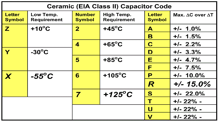
As the reader is probably aware, the capacitance is also going to change over temperature. For reference here is a chart describing this effect for various class 2 dielectric formulations.

So, in new designs, be sure to investigate the published data on voltage and temperature caused variations in capacitance of the parts you intend to use. If the design requires a minimum value of capacitance and the maximum value is of no consequence, choose a large enough capacitance that will never drift down to the minimum. If in any doubt, measure the capacitance of a part while it is placed in the exact conditions of actual use.
About the author:
Terry Conrad has performed 32 years of research, product design and technology management. He has been employed in quality and reliability engineering, design engineering, project management and as president in consumer electronics and military acoustic products design and production firms. Terry is currently an independent consultant, primarily in the fields of acoustics, batteries and component engineering. His clients have included General Dynamics, Molex, Lockheed Martin, Thomson-RCA and many small companies. He can be reached at tconrad@sealandinnovations.com

